
Combing Logic gates into logic circuits
By connecting different logic gates together in various configurations, you can create more complex logic functions and circuits.
Two invaluable uses of logic circuits include:
- Half / Full Adders - some that machines can perform arithmetic
- Flip-flop circuits - some that machines can store data in electronics
For the examination you will need to be able to:
- Draw logic gates and circuits
- Complete truth tables for logic circuits
When evaluating a logic circuit you always work from left to right.
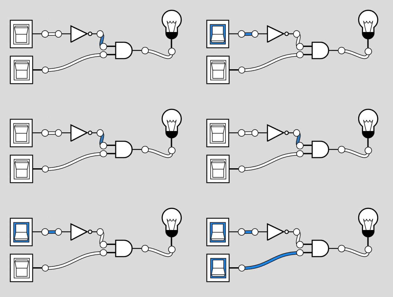
(NOT A) AND B

Here in the example the output of the NOT gate feeds in as an input into the AND gate.
Truth Table
| A | B | not A | (not A) and B |
|---|---|---|---|
| 0 | 0 | 1 | 0 |
| 0 | 1 | 1 | 1 |
| 1 | 0 | 0 | 0 |
| 1 | 1 | 0 | 0 |
Demo
(A AND B) OR C

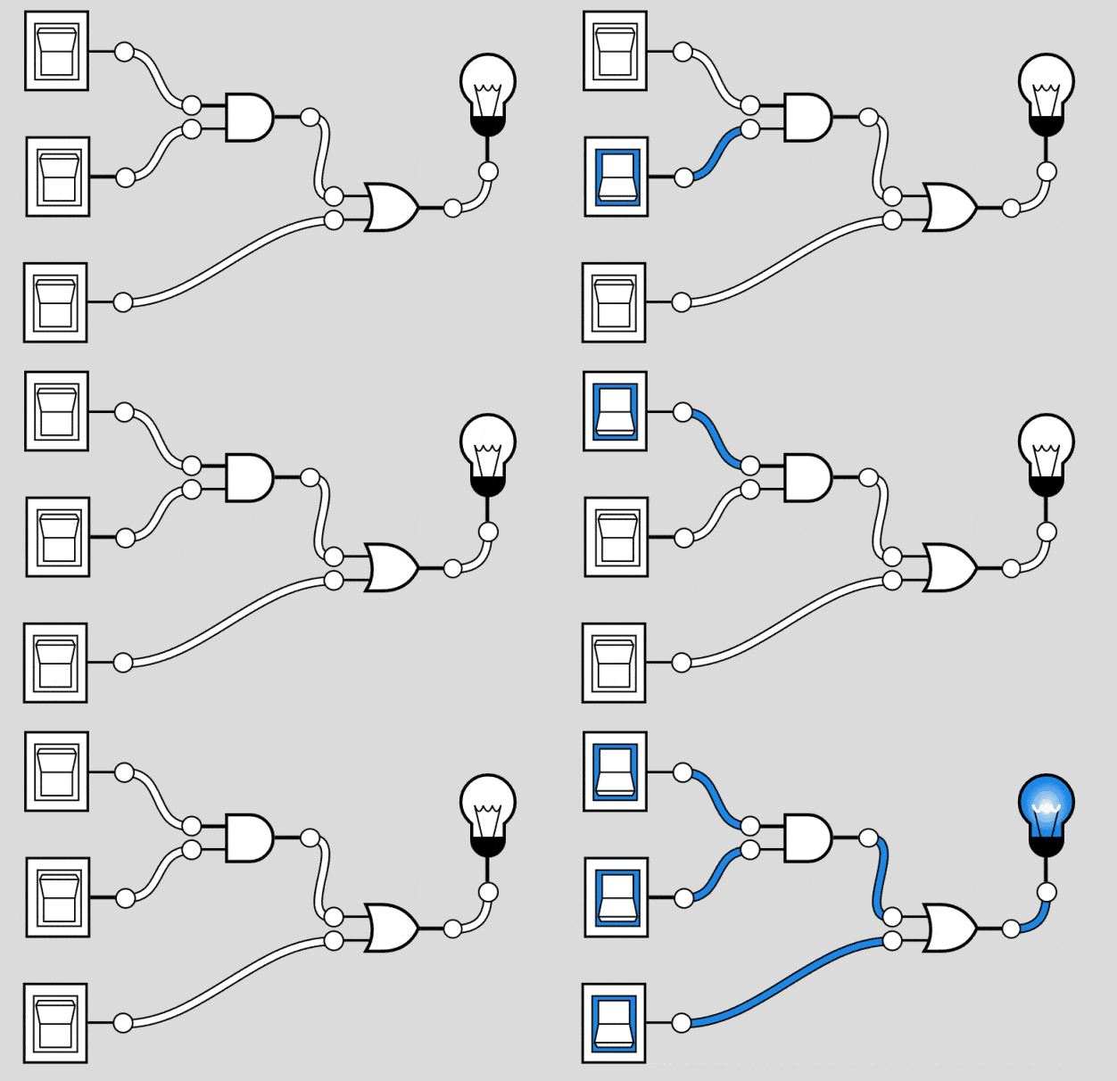
The expression "(A AND B) OR C" represents a logical operation that involves three variables, A, B, and C, along with the AND (AND) and OR (OR) logical operators.
Truth Table
| A | B | C | A AND B | (A AND B) OR C |
|---|---|---|---|---|
| 0 | 0 | 0 | 0 | 0 |
| 0 | 0 | 1 | 0 | 1 |
| 0 | 1 | 0 | 0 | 0 |
| 0 | 1 | 1 | 0 | 1 |
| 1 | 0 | 0 | 0 | 0 |
| 1 | 0 | 1 | 0 | 1 |
| 1 | 1 | 0 | 1 | 1 |
| 1 | 1 | 1 | 1 | 1 |
Demo
Question
Drag gates to canvas:
Input
AND
OR
XOR
NAND
NOR
NOT
Output
Drag gates from the palette above and connect them by dragging from output ports (right side) to input ports (left side). You can branch one output to multiple inputs by connecting from the same output port multiple times.
{"text": "Create a circuit that outputs true when at least one of the inputs A, B, or C is true.", "inputs": ["A", "B", "C"], "booleanSolution": "(A) OR (B) OR (C)"}
Question
Drag gates to canvas:
Input
AND
OR
XOR
NAND
NOR
NOT
Output
Drag gates from the palette above and connect them by dragging from output ports (right side) to input ports (left side). You can branch one output to multiple inputs by connecting from the same output port multiple times.
{"text": "Design a circuit that outputs true when input A is true, input B is true, and input C is false.", "inputs": ["A", "B", "C"], "booleanSolution": "(A) AND (B) AND (NOT C)"}
Question
Drag gates to canvas:
Input
AND
OR
XOR
NAND
NOR
NOT
Output
Drag gates from the palette above and connect them by dragging from output ports (right side) to input ports (left side). You can branch one output to multiple inputs by connecting from the same output port multiple times.
{"text": "Construct a circuit that outputs true when either input A or input B is true, but not both.", "inputs": ["A", "B"], "booleanSolution": "(A XOR B)"}
Question
Drag gates to canvas:
Input
AND
OR
XOR
NAND
NOR
NOT
Output
Drag gates from the palette above and connect them by dragging from output ports (right side) to input ports (left side). You can branch one output to multiple inputs by connecting from the same output port multiple times.
{"text": "Design a circuit that outputs true only when input A is true and input B is false.", "inputs": ["A", "B"], "booleanSolution": "(A) AND (NOT B)"}
Complete! Ready to test your knowledge?
Logic Circuits
- Combing Logic gates into logic circuits
- (NOT A) AND B
- (A AND B) OR C